
Copelametic Compressor Wiring Diagram
Copelametic diagrams model tf* es* esm ts* m 0803 (6) 0900 n 0803 2d 0803 (5,6) 0897 3d 0803, 0816 (4) 0840 0837 (5,6) 0897 Copelametic compressor wiring diagram picture published and published by admin that kept in our collection.

Copeland Compressor Wiring Diagram Wiring Diagram And
Copelametic compressor wiring diagram oleh anonim april 17, 2020 posting komentar electrical.

Copelametic compressor wiring diagram. Copelametic compressor wiring diagram oleh anonim mei 11, 2020 posting komentar electrical. It is very easy to miswire a compressor, but the results can be deadly. This booklet covers, in detail, electrical service information on welded compressors, copelametic® and copeland scroll® compressors.
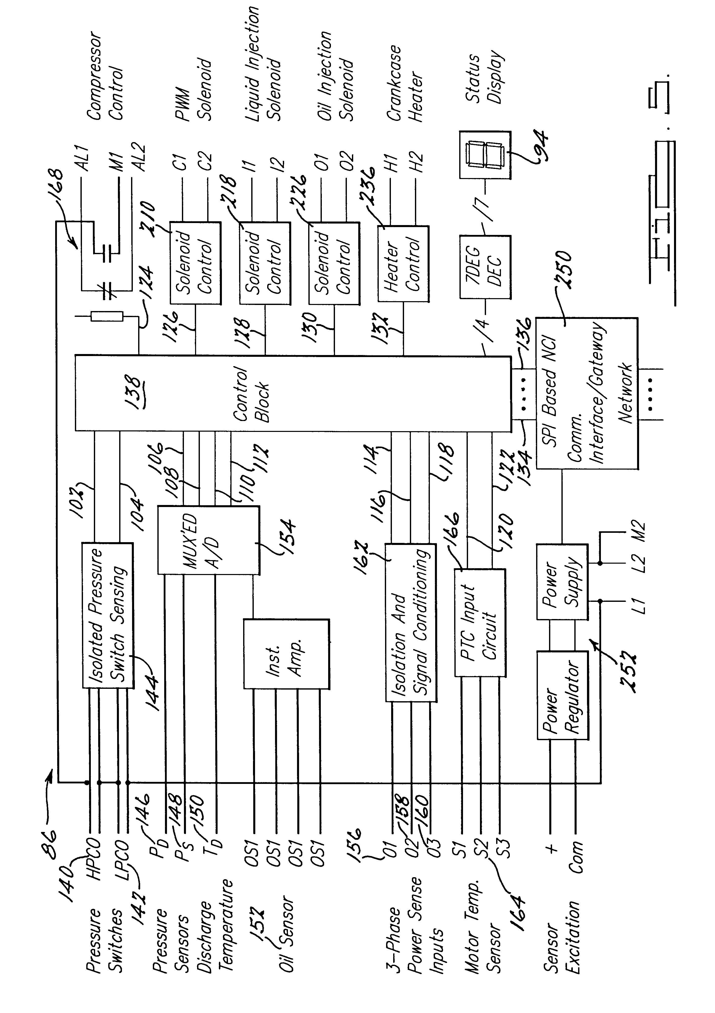
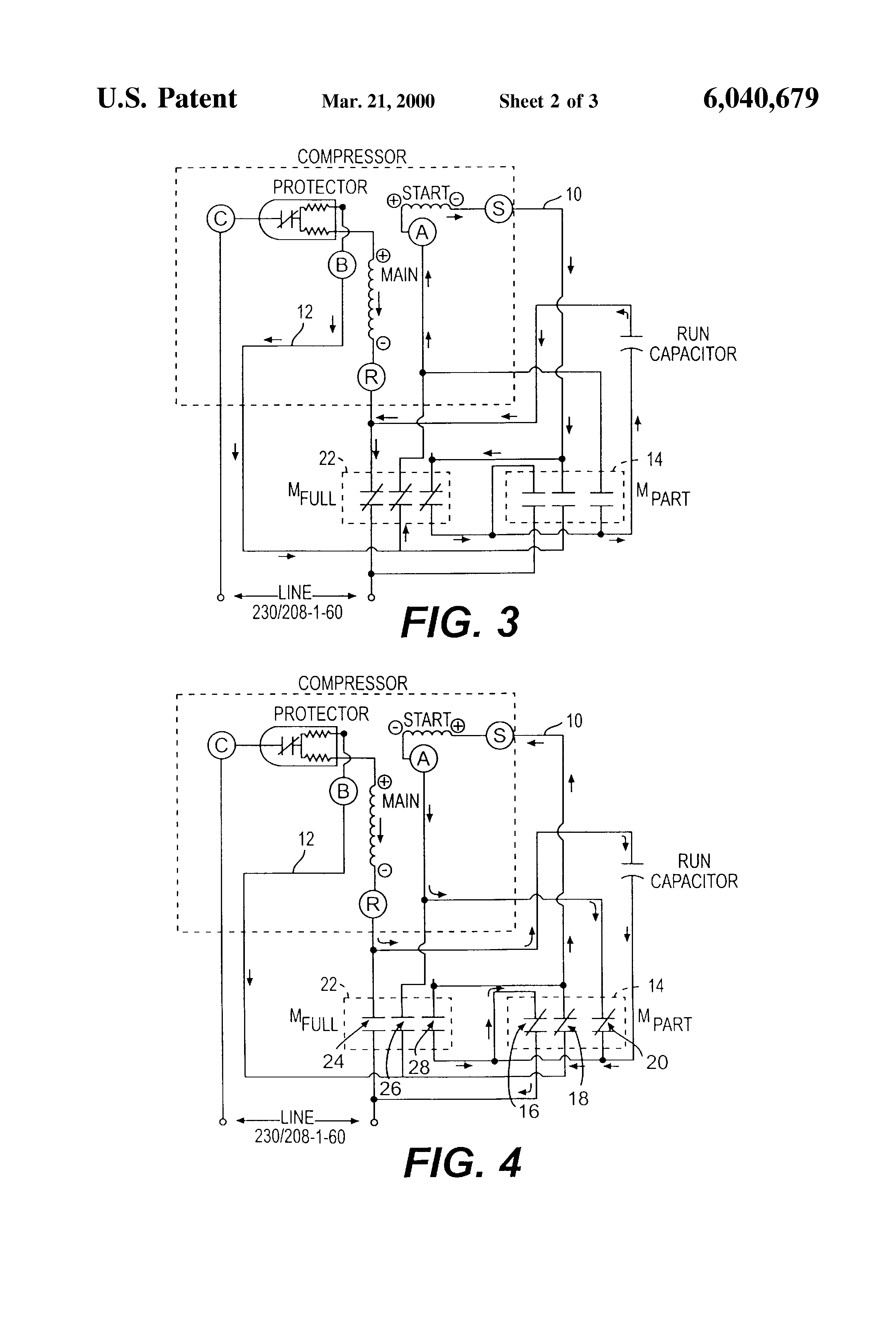
Since each compressor motor operates independently, each compressor may be wired with a separate control system. A simple wiring diagram is shown in figure 3. Copelametic compressor wiring diagram involve some pictures that related each other.
Must coincide with the compressor nameplate. Wrg 2562 audi o2 sensor wiring. A wiring diagram is a type of schematic which uses abstract pictorial symbols to show all the interconnections of components in the system.
Copelametic line is expanded to 30hp with 4 & 6 cylinder models. Standard model 1/4 to 3 h.p. Most use the copeland compressor which usually.
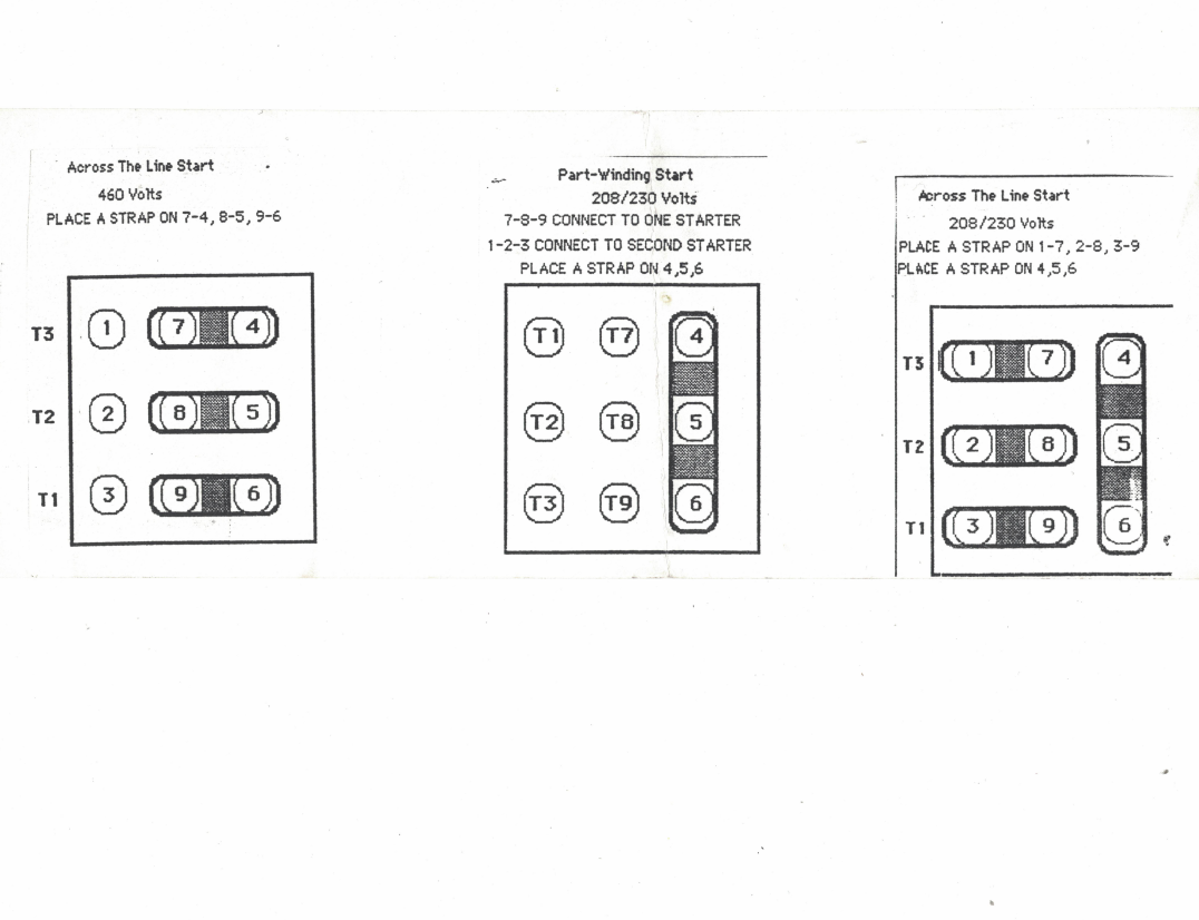
All wiring should be carefully checked against the manufacturer's diagrams. See figure 1 for typical wiring diagrams of tandem units. Circuit wiring diagram 3 phase 460v motor.
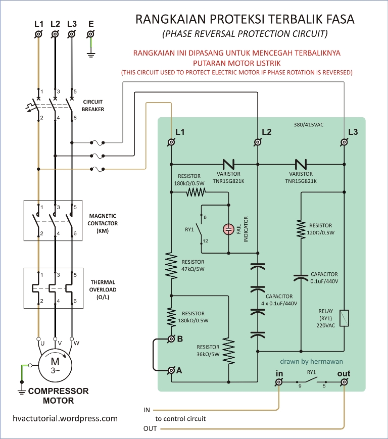
Wrg 2562 audi o2 sensor wiring. Call us at for all your hvac part needs. Note that the oil pressure safety control and dual
Improved starting is realized during a low voltage and/or flooded start If starting current limitation is a problem, a time delay relay may be used to stagger motor starting. I have a kae1 0050 tac copelametic compressor unit 208 230.
Find out the newest pictures of copelametic compressor wiring diagram here, and also you can get the picture here simply. These are indexed against an electrical characteristics code. I have a kae1 0050 tac copelametic compressor unit 208 230.
In addition, electrical service information is provided for copeland® condensing units. Copeland compressor wiring diagram copeland compressor wiring diagram accordance with the position of the capacitors and relay shown on the wiring diagram. There are many air conditioning and heat pump brands in the market but one common component is the compressor.
This is different from a single phase compressor which will have 3 terminals listed as s, r, and c start, run and common. Wrg 2562 audi o2 sensor wiring. The company's stock is listed on the new york stock exchange.
Copelametic compressor wiring diagram oleh anonim mei 11, 2020 posting komentar electrical. I have a kae1 0050 tac copelametic compressor unit 208 230.

Copelametic Compressor Wiring Diagram MILOICEKAW119
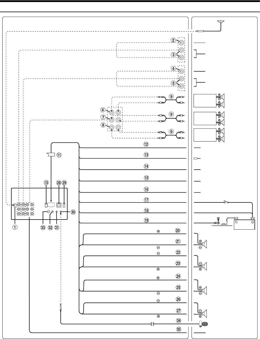
Wiring Diagram For Alpine Ive W530 Wiring Diagram
Bitzer Compressor Wiring Diagram
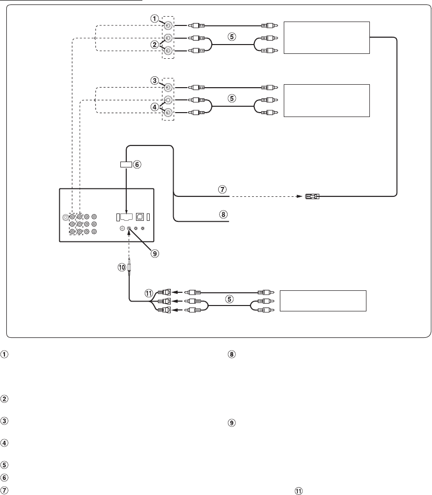
Wiring Diagram For Alpine Ive W530 Wiring Diagram

Copeland Compressor Wiring Diagram Single Phase

Compresor Hermético Scroll Panasonic Sanyo modelo C

Copeland Scroll Compressor Wiring Diagram For Your Needs
31 Copeland Scroll Compressor Wiring Diagram Wiring
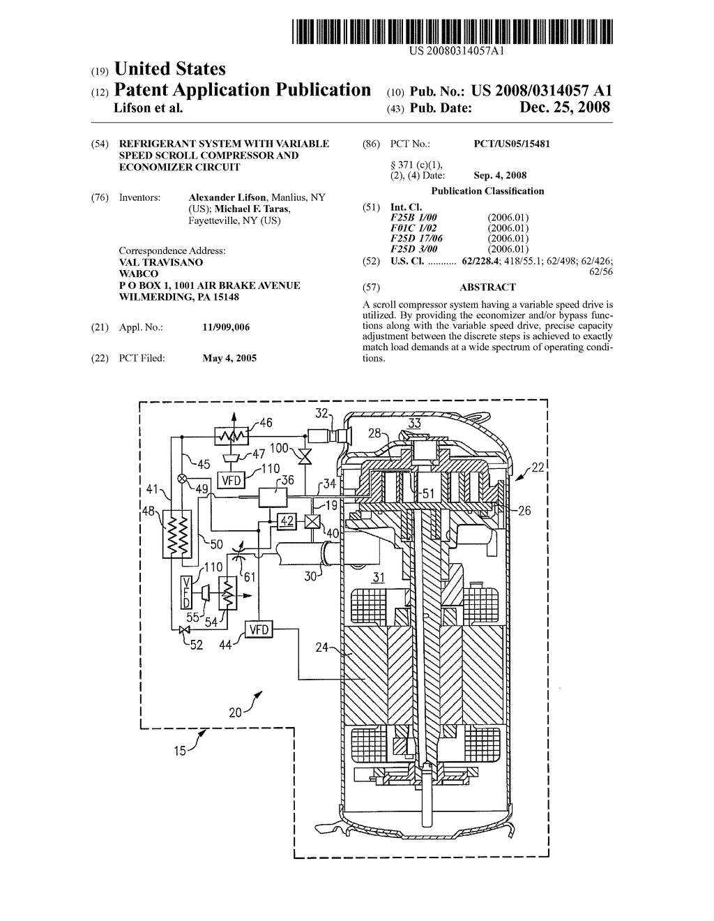
Reference Materials GFA Compressors

Pressure Switch Wiring Diagram Air Compressor Wiring
Bitzer Compressor Wiring Diagram
Refrigeration Copeland Compressor Wiring Refrigeration
Copeland Compressor Wiring Diagram
Copeland Hermetic Compressor Wiring Diagram Wiring Diagram

Copeland Compressor Wiring Diagram Single Phase

Copelametic Compressor Wiring Diagram MILOICEKAW119
34 Wiring Diagram For Copeland Compressor Wiring Diagram

Fac Compressor Wiring Diagram 150 Wiring Diagram & Schemas

Copelametic Compressor Wiring Diagram MILOICEKAW119
