
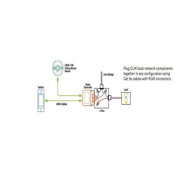
Wattstopper Lmdc 100 Wiring Diagram
All electrical installation work should be carried out by an experienced electrician. The dw dual technology wall switch sensor combines the wattstopper's dual technology has the flexibility to work in a.

Wattstopper Occupancy Sensor Wiring Diagram Wiring
Local, and national electrical codes and requirements.

Wattstopper lmdc 100 wiring diagram. Component of digital lighting management integrated control. Turn the power off at the circuit breaker. Input voltage ballast(a) incan(a) motor(hp) output.
All wiring must comply with applicable electrical and safety codes. 26.11.2018 26.11.2018 7 comments on wattstopper pw 100 wiring diagram. Strip gage 1/2 12.7mm visit our website for faqs:
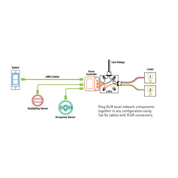
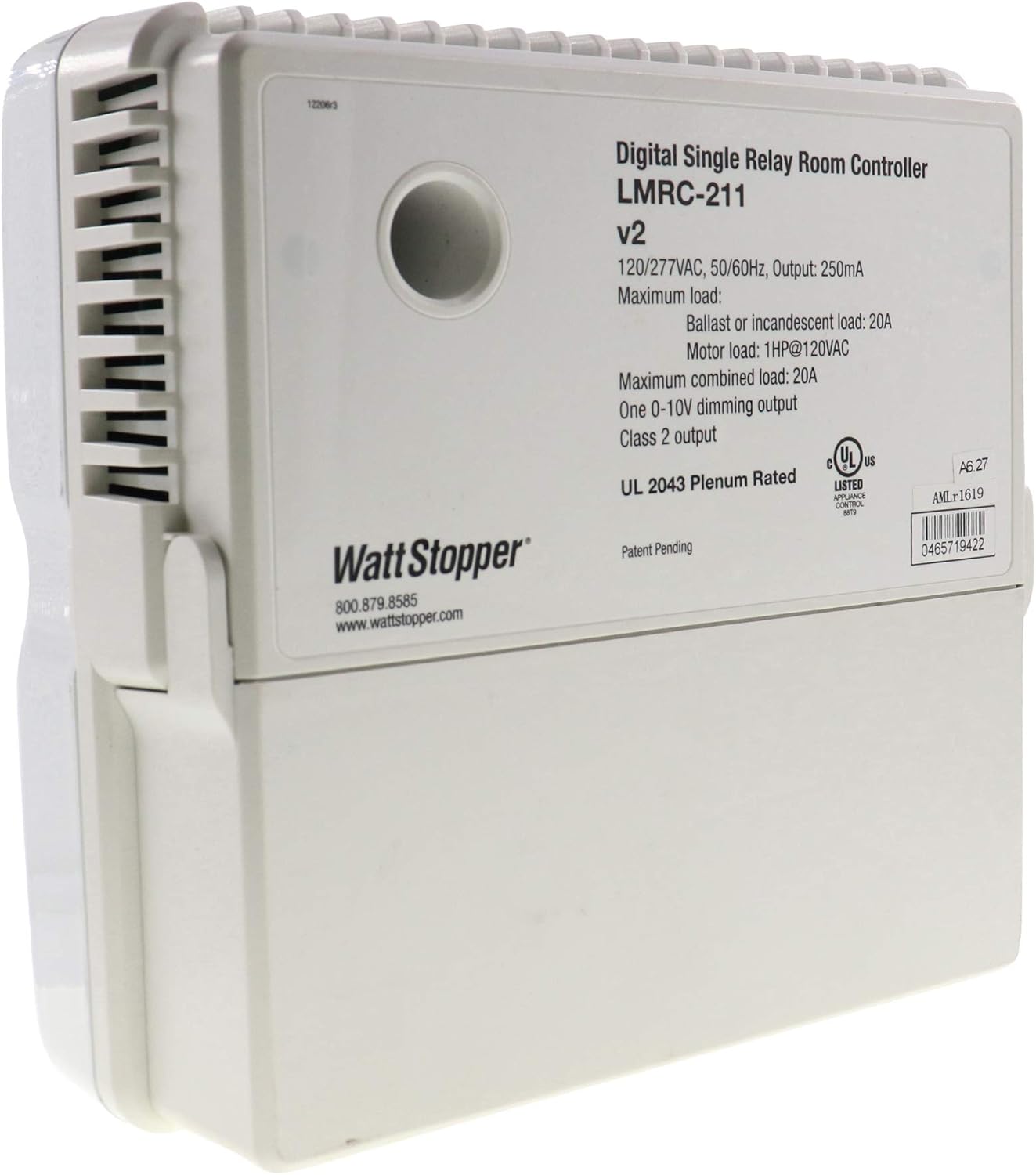
Before installing the sensor or working on the load.! Connect the power wire from the lamp (load) to the red wire on the cu. Lmrc digital on/off/ volt dimming room controller with 1 relay and 1.
1) all wattstopper power packs should be installed in accordance with state. The sensor multiple sensor wiring diagram. System low profile design for.
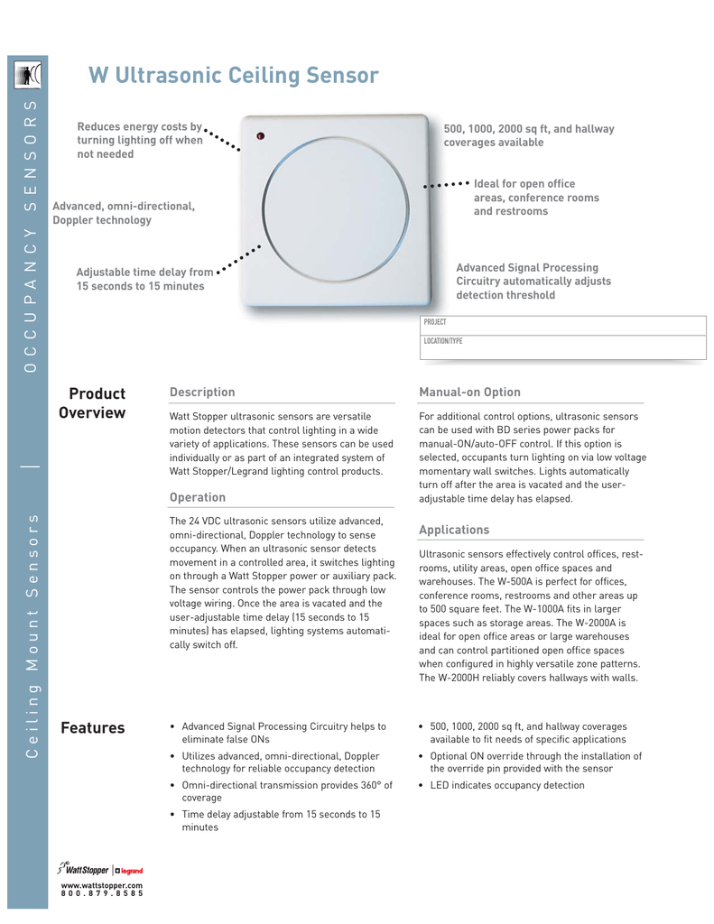
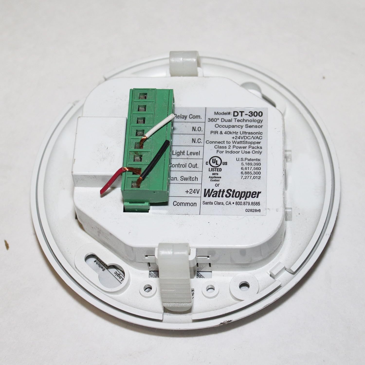
Visit wiringall.comopper/com/dlm and download sales dlm and roi to obtain the. The dt operates on 24v supplied by the watt stopper power packs. For best performance, wattstopper recommends
Assumes a basic knowledge of good wiring practices. The pw passive infrared (pir) wall switch sensor can turn wiring diagrams. Refer to the wiring diagram on the next page for the following procedures:
Visit our website for faqs: Pw & pw 2 0 / 2 3 0 / 2 7 7 vac, 50/60hz. The segment manager can be placed at the end of the segment network as shown in the previous block diagram, or it can be located anywhere along the linear network.
When using more sensors than this, multiple power packs are required. To increase or decrease the lighting level. Note that the normal power sense connection should be made to the line side of the control device that serves the same area as the emergency lighting.
All wiring must comply with applicable electrical and safety codes. It is a digital sensor, and is part of a wattstopper digital lighting management (dlm) system. Long range lens, up to 90 ft.
They are the foundation of a wattstopper digital lighting management (dlm). • red wire (+24vdc) from power pack to the +24v terminal on the sensor. Circuit as shown in the wiring diagram.
All units should be on the same phase. It is a digital sensor, and is part of a wattstopper digital lighting management (dlm) system. No neutral connection catalog no.
Almond ivory grey black 120/277 vac; This ensures that the emergency lighting in. For best performance, wattstopper recommends using this sensor in spaces no larger than 15' x 12'.
Refer to the wiring diagram on the next page for the following procedures:

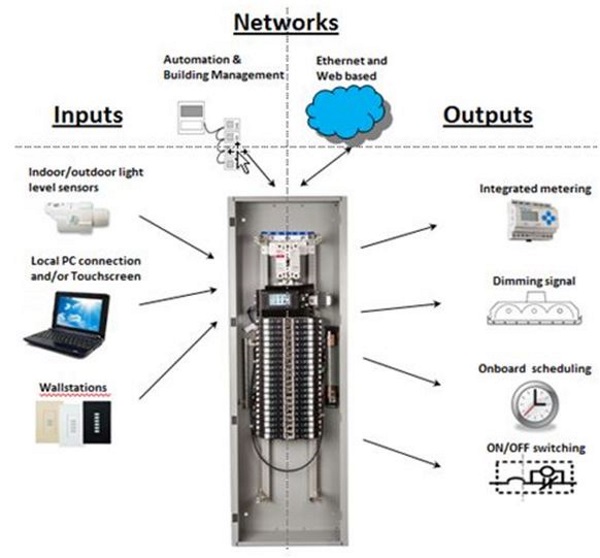
Watt Stopper Relay Control Panel Wiring Diagram Complete
Wattstopper Occupancy Sensor Wiring Diagram Wiring
Wattstopper Wiring Diagram Complete Wiring Schemas


√無料でダウンロード! rh786r wiring diagram 332628Rh786r wiring

Wattstopper Occupancy Sensor Wiring Diagram Wiring
Wattstopper How to Setup a room with multiple dimmers
LMRC100 SERIES DIGITAL SWITCHING ROOM CONTROLLER
WattStopper Occupancy Sensor DSW200W eBay

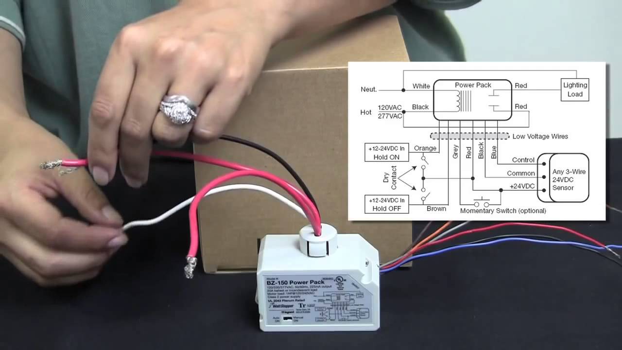
How to Wire the BZ 150 Universal Voltage Power Pack from
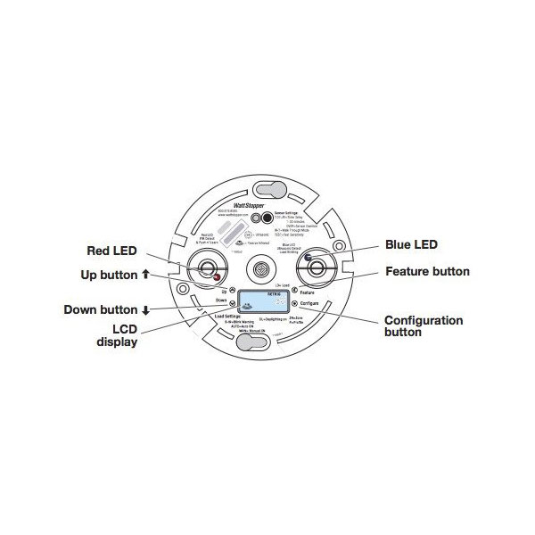
LMDC100 DUAL TECHNOLOGY CEILING MOUNT OCCUPANCY SENSOR
Watt Stopper Relay Control Panel Wiring Diagram Complete
Watt Stopper Relay Control Panel Wiring Diagram Complete
√無料でダウンロード! rh786r wiring diagram 332628Rh786r wiring

Watt Stopper Relay Control Panel Wiring Diagram Complete

LMPC1005 Occupancy Sensor, WattStopper Architect Magazine

Wattstopper LMPC100 PIR Digital Occupancy
Wattstopper Ceiling Mounted Dual Technology Occupancy
LMDC100 DUAL TECHNOLOGY CEILING MOUNT OCCUPANCY SENSOR
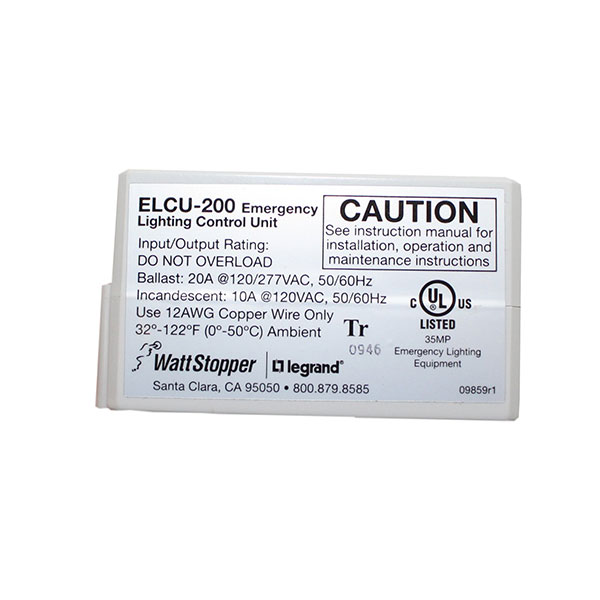
ELCU200 EMERGENCY LIGHTING CONTROL UNIT LiteRite Controls
